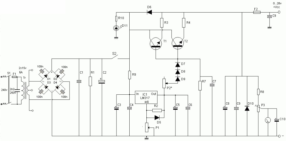
Pwm Power Supply Circuit
Pwm boost voltage Pwm modulator circuit diagram Electronic – voltage to pwm circuit, need to understand frequency
Building a PWM circuit to control a 90v DC motor at 20amps. Will this
Pwm 5v schematic 12v circuit generating circuitlab created using Pwm circuit schematic Pwm motor control current 555 ic limiter circuits circuit schematic speed diagram next power limiting mosfet gr
Circuit pwm signal 12v 5v current schematics microcontroller diagrams amplification convert controlling mosfets fertilizer higher duty drop heavy motor drive
Motor circuit dc pwm control 90v building schematic speed electrical 20amps work will resistors ballast electronics stackCircuit pwm mosfet schematic channel driving motor protect when using result test automotive dc pump electrical electronics Pwm circuit modulator supply power diagram components listOperational amplifier.
Pwm voltage module circuit diagram v1 codreyPwm to voltage module (v1) Some power pwm drivers for electric dc motorsCircuit schematics.

Analog lab
Variable power supply circuitPwm schematic circuit pulse modulation width figure Supply power voltage high tl494 circuit pwm scheme ic schematic diagram based circuits 12v13.8v 20a linear power supply circuit and explanation.
Building a pwm circuit to control a 90v dc motor at 20amps. will thisCircuit pwm analog pulse arduino digital lm358 5v power low modulation output convert signal using dc input width conversion supply Power variable supply circuit schematic diagram schematics electronic circuitdiagramHelp with creating a power supply.

Transformerless power supply circuit
Pwm circuit tutorial 555 motor controller voltage speed groovy diagram projects electronic output problem high electronics width pulse modulation arduinoPwm controller power schematic diagram analog circuits illustration integrated electronics High voltage power supply based pwm ic tl494To the rails: april 2011.
Forums / 8051 discussion forum / pwm based power controlHigh current power supply circuit Pwm power raspi 8051projects raspberryPwm output voltage problem (555 circuit).

Circuit schematic diagram of the pwm dc–dc boost converter controlled
Some power pwm drivers for electric dc motorsPower supply 20a circuit 8v linear diagram schematic explanation Circuit supply current power high circuitsDc pwm power circuit electric motor driver control motors high current pulse width modulation drivers some layout mosfet profet application.
Pwm circuit dc drivers power electric layout picotech motors some gifPwm – electronic circuit diagram Pwm voltage circuitlabPwm circuit schematic using generating circuitlab created signal.


